MRX

Applications

implemented in

Products

Our MRX - Applications

The MRX Applications represent an innovative solution for a wide range of applications in the most diverse areas of use. In this overview, we offer you a comprehensive presentation of the three main modes – Flow Mode, Shear Mode and Wedge Mode. Each of these modes is not only explained in detail, but also supplemented by clear, practical examples that illustrate their respective strengths and application potential. This combination of detailed explanation and practical illustration enables you to gain an in-depth understanding of the functionality and versatility of our MRX technologies and to make optimum use of them for your specific requirements.

Graph showing the working range of a linear damper
Figure 1: Working range of a linear damper

Magnetic flux through the effective gap of an MRF Valve

In flow mode, MR fluid is conveyed from the high-pressure side to the low-pressure side due to an actuating movement in a mechanical system. The fluid is pressed through relatively low channels, which are magnetically flooded perpendicular to the direction of movement. This results in a hydraulic pressure loss during the flow due to the viscosity and, in addition, magnetic shear stresses become effective, which in total impose a certain pressure loss on the system (MRF valve).

Magnetic flux density and velocity distribution in the effective gap of an MRF valve, including cross-sectional view and magnetic field simulation.
Figure 2: Magnetic flux through the effective gap of an MRF valve: area between housing and coil core

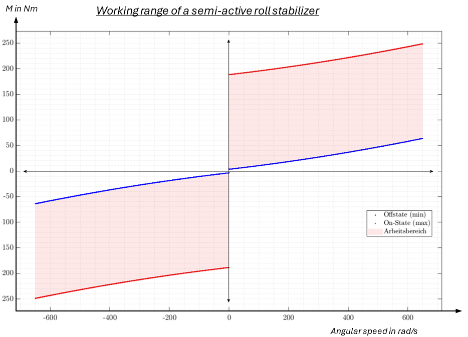
The ON-OFF state diagram (I=Imax or I=oA) shows the usual behavior of an actuator operated in flow mode with the basic hydraulic damping (green characteristic curve) and the maximum damping via the additional MR effect (orange characteristics curve). The range between the two characteristic curves can be varied via control from 0-100% of the maximum oil current.


The great advantage over purely hydraulic actuators is that, on the one hand, high forces/tourques can be generated even at no speed and on the other hand, an entire working range can be used variably.

Diagram showing the working range of an actuator in flow mode
Figure 3:Working range of an actuator operated in flow mode

Linear flow mode - Damper Solutions

Linear MRF dampers are similar in design to linear fluid viscous dampers and use MR fluids instead of hydraulic oil. The main components are the cylinder and the piston that moves linearly within it. In the cylinder, a separating piston separates the area of MRF fluid and gas, with the gas serving as a compensation volume for the immersing piston rod or the temperature and leakage. When the piston is moved in the cylinder, the MRF fluid flows through the piston. In an MR damper, the piston contains a coil (with the exception of an external valve) that generates a magnetic field in the flow channels of the piston (see Figure 4: linear MRF damper in section).

3D section view of a linear MRF damper with detailed labeling of internal components
Figure 4: Linear MRF damper in section

The piston with the magnetic field-loaded flow channels can be regarded as a „magnetorheological valve“, in which the viscosity can be varied from liquid to semi-solid by energizing the coil. Depending on the magnetic field as a result of the coil current, a certain damping behavior or linear force of the damper is created in the piston, which can be easily adjusted without having to change the mechanical structure of the system. The great advantage of this is that high forces can be transmitted without speed and the entire working range of the MR fluid can be utilized.

In principle, there are the following design implementation options analogous to fluid hydraulics:

Depending on the design of the compensation volume or the design of bypasses (direction-dependent additional channels) in the system or the design of the coil, e.g. with a permanent magnet, it is possible to influence the characteristic curve.

INVENTUS designs the dampers according to customer requirements and adapts the design implementation to the desired characteristic curve requirements. A few different design options are shown below, which describe possible versions of an MR linear damper.

Section view of a linear damper with a permanent magnet positioned between the core halves
Figure 6: Section of linear damper with permanent magnet (between the core halves)


The diagram shows a force-displacement diagram of a linear damper with an installed permanent magnet with a travel speed of 65 mm/s. The diagram Fig. 6 illustrates how a fail-safe function can be implemented in the currentless state = 0A (fail-safe function: basic force at 0A); the effect can be increased by applying current, as shown with 1A, 2A and 3A, but a reduction down to the minimum basic force is also possible with a corresponding negative current (not shown).

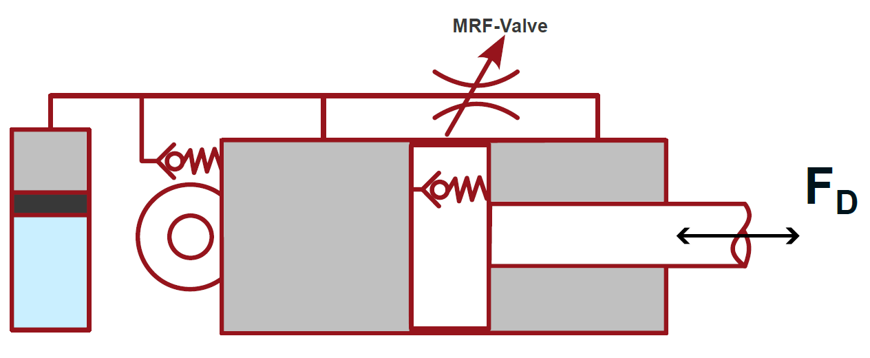
The bypass, which is effective in the tension stage, enables low-friction resetting in the tension direction regardless of the current applied, as it is not subjected to the magnetic field.

Force-displacement diagram of a linear damper with a permanent magnet
Figure 7: Force -displacement diagram of a linear damper with permanent magnet

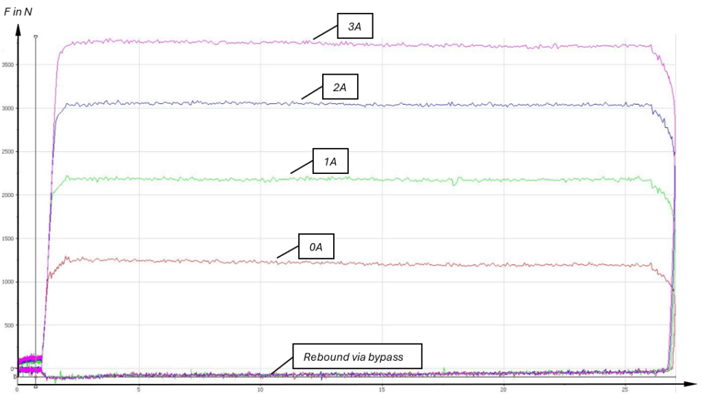
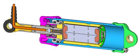
With the damper concept shown here with a cylinder inner diameter of 30 mm, over 3500 N can be achieved at low speeds, while the basic force (friction of piston rod seal/piston guide ring/separating piston) amounts to approx. 35 N (with permanent magnet with corresponding negative current), which corresponds to a spread of maximum force to basic force by a factor of 100.

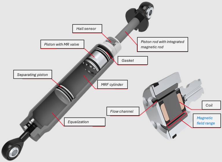
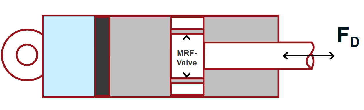
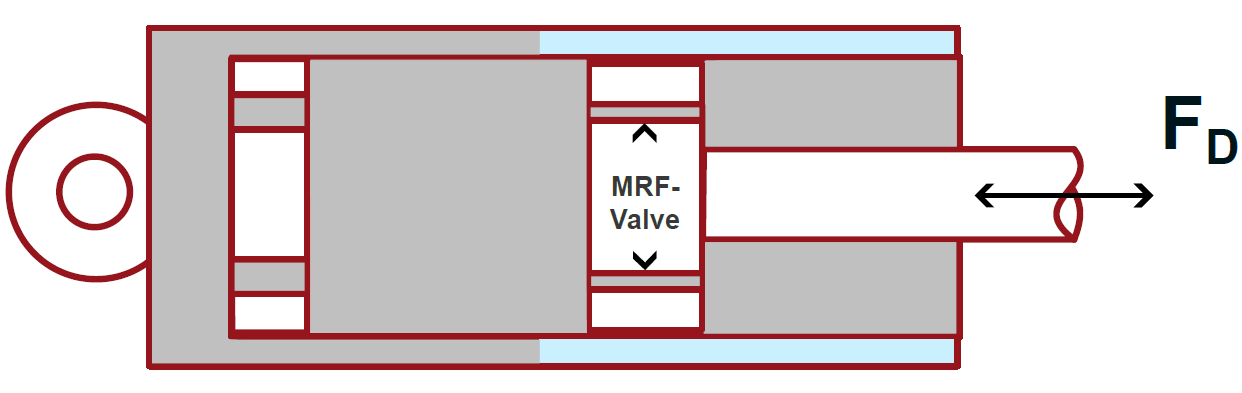
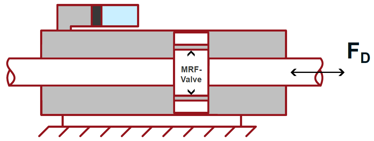
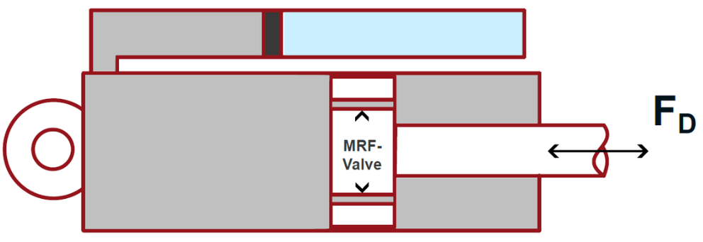
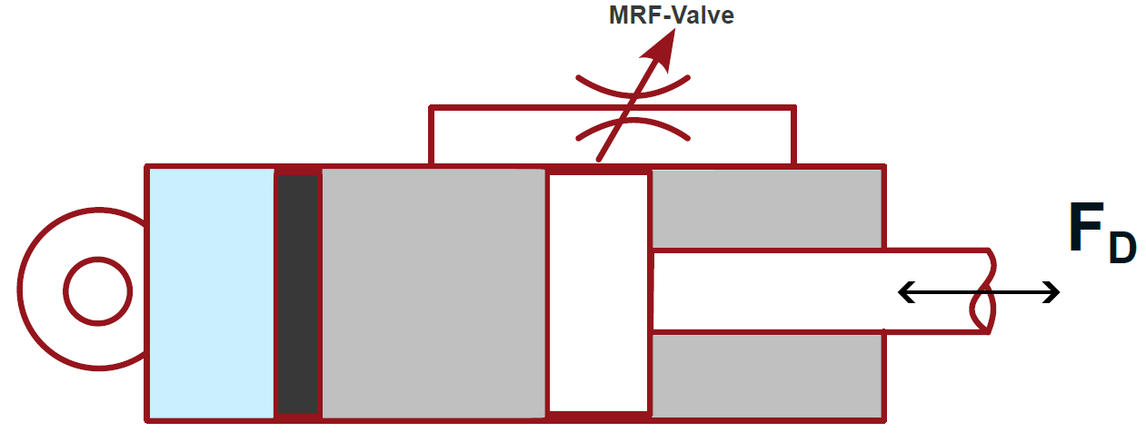
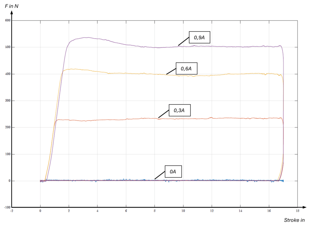
However, even higher spreads of maximum to basic force can be achieved under certain circumstances, shown here by using an externally arranged valve. In this approach, the MRF valve is not located in the piston but externally; the piston merely serves as a displacer and displaces the MR fluid, which flows back into the system in a circuit via the external valve.

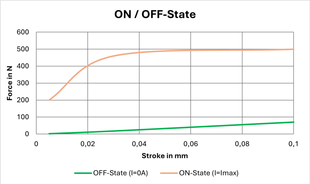
In this specific very small application (inner cylinder diameter <10 mm), the aim was to achieve an extremely low basic force of approx. 2 N and yet up to 500 N locking force could be realized. This corresponds to a spread ratio of 250.

Force-displacement diagram of a linear damper with external valve, showing forces at current levels from 0A to 0.9A.
Figure 8: Force displacement diagram of a linear damper with external valve

Here is an example of a successfully implemented product that uses exactly this technology.

Rotative flow mode with limited angle - MRF rotary damper

The counterpart to the linear damper solution in the rotary view is the MRF rotary damper, whereby a rotary blade is mounted centrally in the housing and can only perform a certain rotary angle (analogous to the stroke in linear technology).

The visible gap is filled with MR fluid, if the rotary blade is turned, MR fluid is conveyed from the high-pressure side via the effective gap to the low-pressure side, as with the piston in linear technology.

The two side covers contain the coils, store the system and seal the system from the outside, so the system consists of very few parts

Main components of an MRF rotary damper, labeled parts including vane, housing, and working gap.
Figure 9: Main components of the MRF rotation damper

The differential pressure between the two chambers resulting from the flow or the magnetic shear stresses is primarily reduced in the effective gap – “magnetorheological valve”. This is not realized in the moving component as with the piston in linear technology, but is formed by the adjacent surfaces of the housing to the rotary blade (red area Fig. 10).

The rotary blade itself is mounted on a swivel sash, which enables relative rotation and defines the shear zone for the MR fluid. It is also necessary to seal internally to the inner ring diameter as well as to the adjacent end faces (blue marked areas 3D view), but MR technology has the great advantage of magnetic sealing, in which the MR fluid has a self-sealing effect in the presence of a magnetic field. This is an essential advantage of the MR rotary damper compared to the hydraulic state of the art, especially in terms of tightness and service life. It also reduces manufacturing costs (lower requirements for tolerances, surface roughness and hardness).

3D cross-sectional view of an MRF rotary damper showing labeled components such as housing, vane, and lid with coil.
Figure 10: 3D view of MRF rotary damper in section
Operating range of an MRF rotary damper, showing hydraulic pressures and internal moments of the damper.
Figure 11: Working area MRF rotation damper

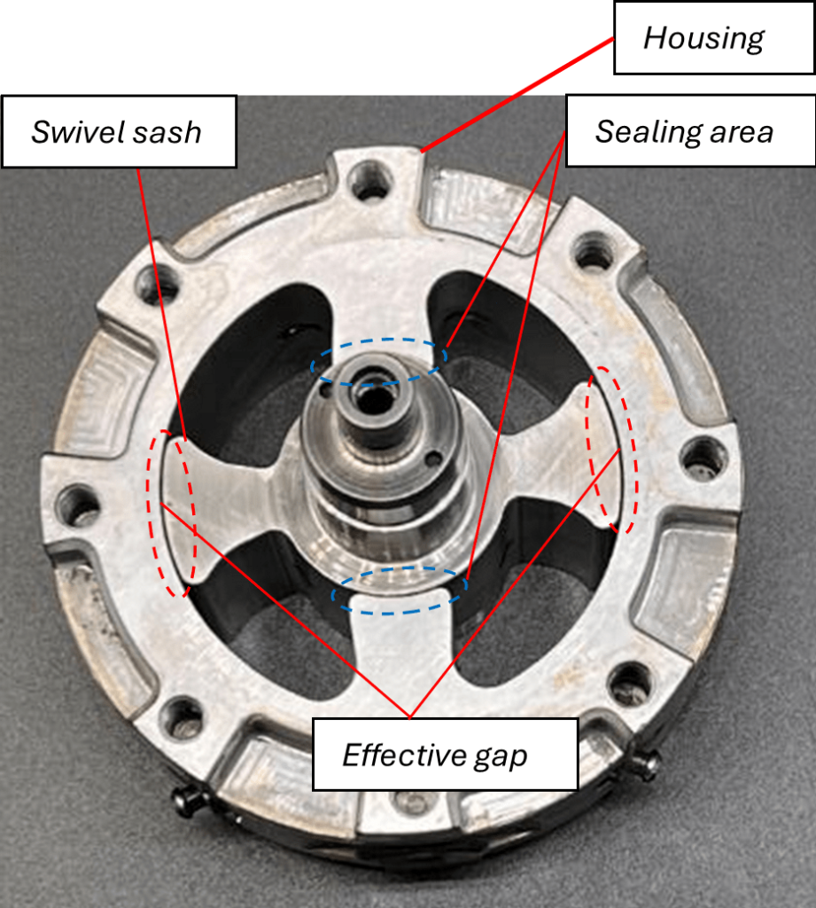
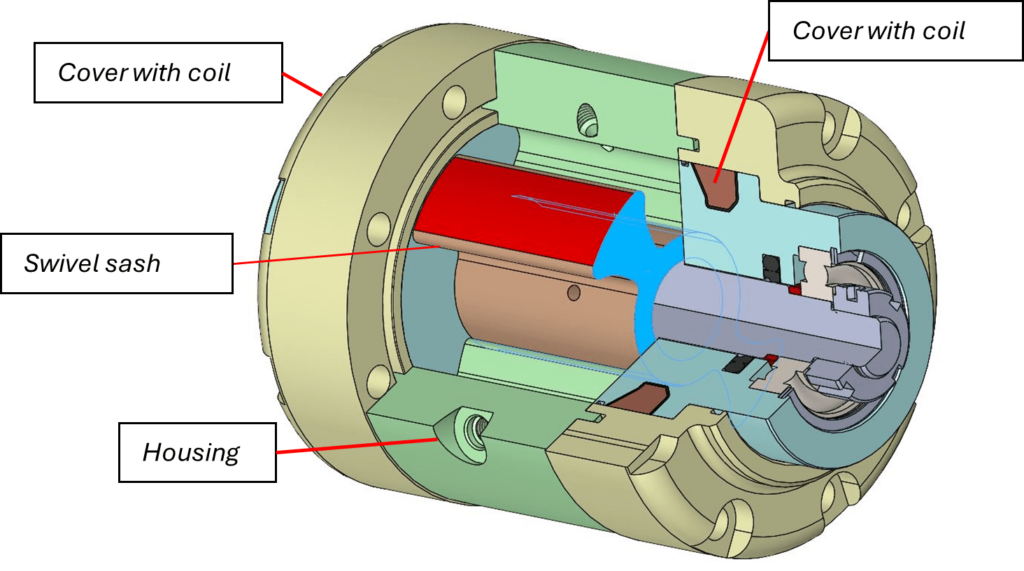
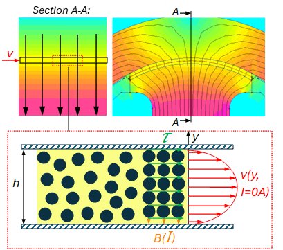
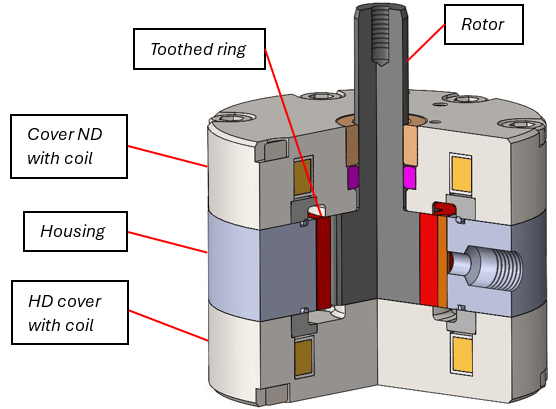
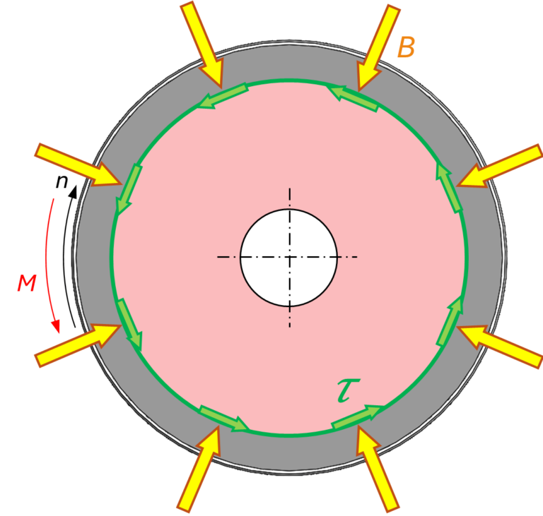
The acting magnetic field is generated by the two coils integrated in the covers and ensures that the entire rotary blade is magnetically flooded at right angles to the flow gap or the leakage gaps and that the iron particles align themselves in the direction of these magnetic field lines. Here, too, the viscosity can be varied from liquid to semi-solid in the rotary application and, depending on the magnetic field as a result of the coil current, a certain damping or torque is created in the rotary blade, which can be easily adjusted without having to change the mechanical structure of the system. A major advantage is that high static torques can be transmitted and the entire working range can be utilized – magnetic effects are superior to hydraulic effects.

Different designs of rotor discs for an MRF rotary damper, schematic representation of variations.
Figure 12: Different versions of MRF rotation dampers


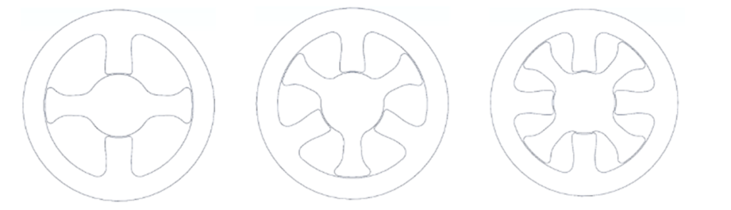
Depending on the existing rotary angle or necessary torques, 3 or 4 wings can also be implemented instead of the 2-wing rotary wing shown (approx. 95° rotary angle), for example, but only partial angles can be used without mechanical transmission.

Graphical illustration showing the working range of a semi-active roll stabilizer
Figure 13: Working range of a semi-active roll stabalizer


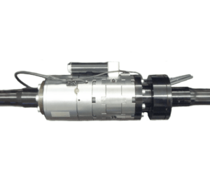
As with linear technology, INVENTUS designs corresponding pivoting vane solutions according to customer requirements and adapts the design implementation to the desired torque characteristic requirements, such as permanent solutions.

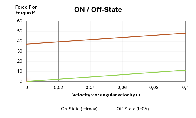
A concrete implementation is shown on the basis of an illustrated working range of a two-wing system of a roll stabilizer and describes the torque present as a function of angular velocity.

Here is an example of a successfully implemented products that use exactly this technology.

Anti-Roll Bar

High-tech anti-roll bar system featuring a compact actuator and sensor integration for advanced vehicle stability.

Rotary Damper

Cross-sectional view of an adaptive rotary damper, showing its internal components, including a red rotating shaft and surrounding damping elements.

Viodeo explanation of the MRF rotary Damper

This section is password protected!

To get access to it, please contact Inventus-Development!

Rotative flow mode with unlimited angle - MRF - Pump

The MRF pump shown works very similarly to a gerotor pump and implements a rotary MRF damper application with an unlimited angle. The rotor drives a toothed ring mounted centrally in the housing. Due to the geometry, the outer toothed ring always rotates by the pitch of one tooth less than the rotor, whereby the enclosed crescent-shaped tooth gaps filled with MRF always experience a chamfer of suction or compression during a rotor revolution – MRF is pumped.

Figure 14: Main components of the MRF pump

In order to position and seal the 3 components rotor, toothed ring and housing in relation to each other, the unit is closed with 2 covers. Both covers contain 2 coils for the magnetic flux as well as specially shaped kidney-shaped pockets to connect the low and high pressure areas of the rotor. In order to realize the corresponding crescent-shaped tooth gaps to the tooth ring and thus the pump effect with the rotor, the bearing of the rotor is eccentric to the rest of the construction. This pumping effect is used internally to relieve the pressure generated in an MRF valve (circular gap between tooth ring and housing – green dotted area Fig. 15 right), whereby the magnetic influences are again dominant over the hydraulic influences.

3D section view of an MRF pump showing internal components
Figure 15: 3D view of MRF pump in section

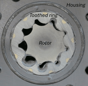
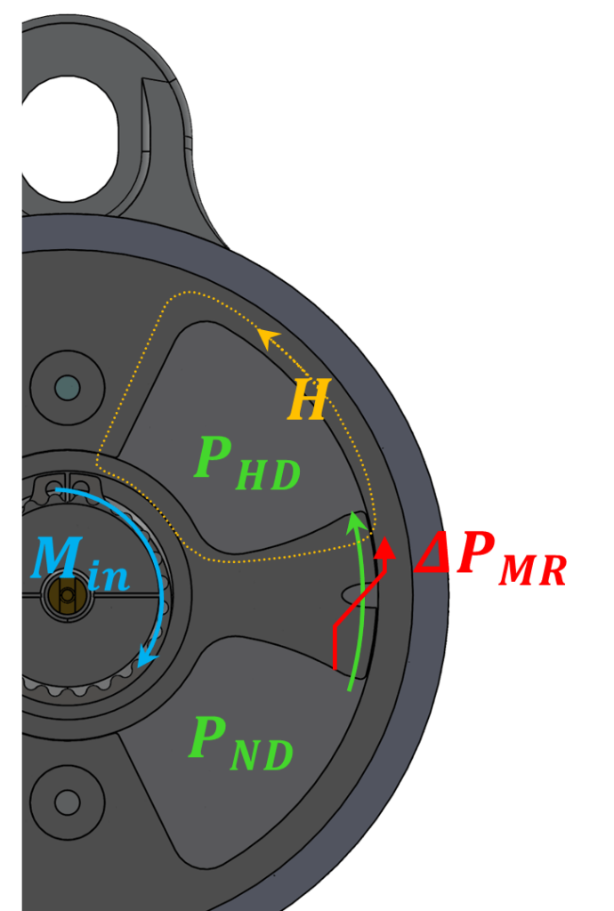
If you mentally start at the green point (Fig. 15 all 3 views) in the high-pressure area, the MRF has the highest pressure there due to the strong compression – the medium is virtually „pressed“ out of the gap through the increasingly smaller toothed gap (see Fig. 15 right) and flows into the pocket formed in the HP area in the lower cover, is distributed around the circumference and flows through the circular gap (MRF valve) into the upper LP area, where the medium is sucked in again by the gearing through the opposing kidney pockets in the upper cover.
is sucked in again.

3D visualization of the hydraulic circuit or working range of an MRF pump
Figure 16: Explanation of the hydraulic circuit or working range of the MRF pump


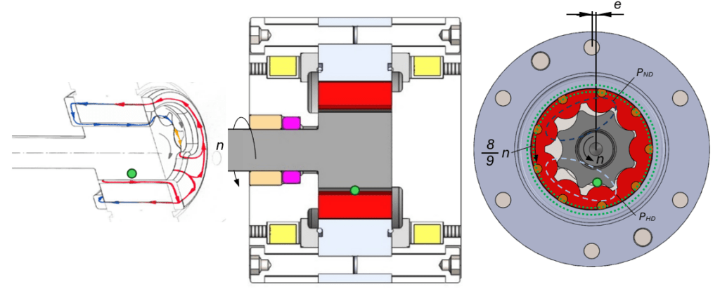
Here, too, the MRF pump is sealed by means of the orthogonal magnetic field lines hitting the gaps, and the annular gap is also controlled as an MRF valve and the magnetic influences dominate over the hydraulic influences.

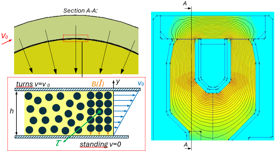
It must be correctly added that this is not 100% pure FLOW mode, as the MRF particles are also squeezed to a certain extent in the working area and therefore an additional squeeze mode is effective.  

Shear Mode or MRX shear damper (MRF or MRP)

In shear mode, fluid is not conveyed through a gap as in flow mode, but one mechanical component moves towards the other; in the case shown here, this is a housing that rotates around a stationary axis, but the design can also be reversed (see Fig. 19: Rotor rotating in the housing). The fluid experiences an almost linear velocity profile and the magnetic field flows through it perpendicularly.

Magnetic flux simulation in the effective gap of an MRX shear attenuator, illustrating field distribution between housing and coil core
Figure 17: Magnetic flux through the effective gap of an MRX shear attenuator: area between housing and coil core

In shear mode, the speed-dependent losses in our usual applications are even more significantly reduced compared to flow mode and can therefore be neglected with a good approximation and thus purely the existing shear stresses on the shear surface (Fig. 17 Annular gap in green) determine the existing torque on the actuator.

Cross-sectional view of an MRX shear damper. The arrows indicate the direction of magnetic flux density B and torque M. Shear forces τ act on the rotating body, with the rotational speed n indicated by the arrow direction.
Figure 18: MRX shear damper in section

The ON-OFF state diagram shows the usual behavior of an actuator operated in shear mode with the basic hydraulic damping (green characteristic curve) and the maximum damping via the additional MR effect (orange characteristic curve). The range between the two characteristic curves can be varied via control from 0-100% of the maximum coil current.

Diagram showing the working range of an actuator operated in shear mode
Figure 19: Working range of an actuator operated in shear mode


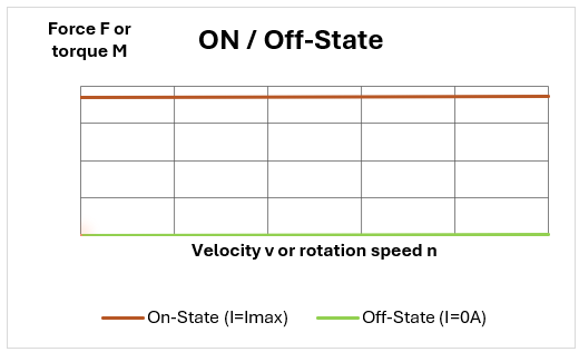
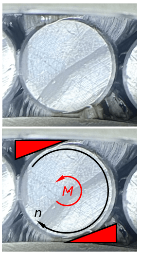
The big advantage over flow mode here is that the basic friction in particular can be kept very low due to the almost „speed-independence“ (OFF-state characteristic curve). This variable force/torque curve from 0 in milliseconds makes the application very interesting for haptic elements.

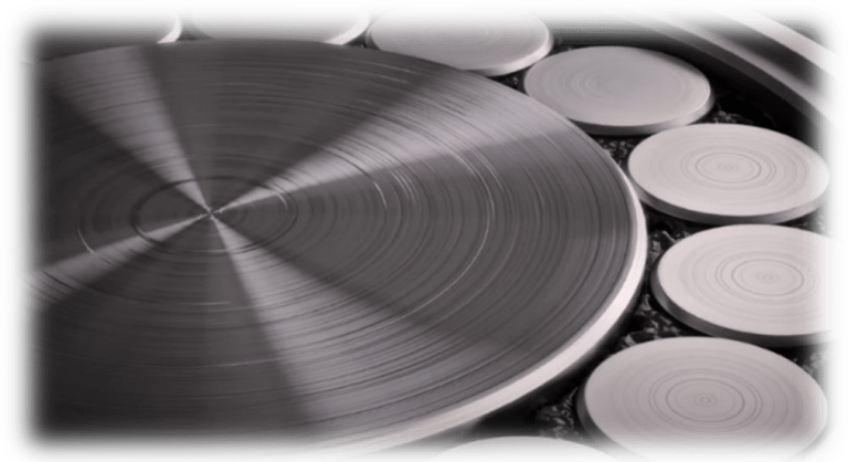
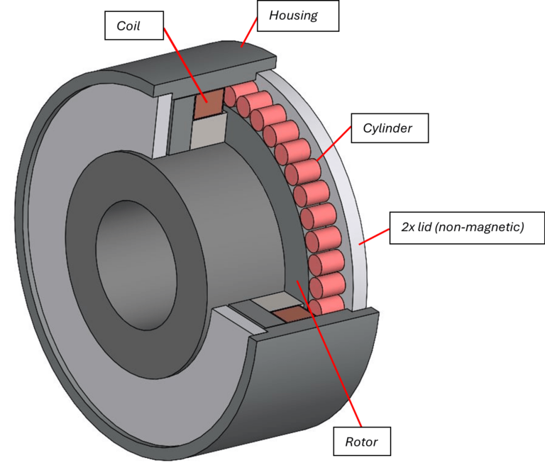
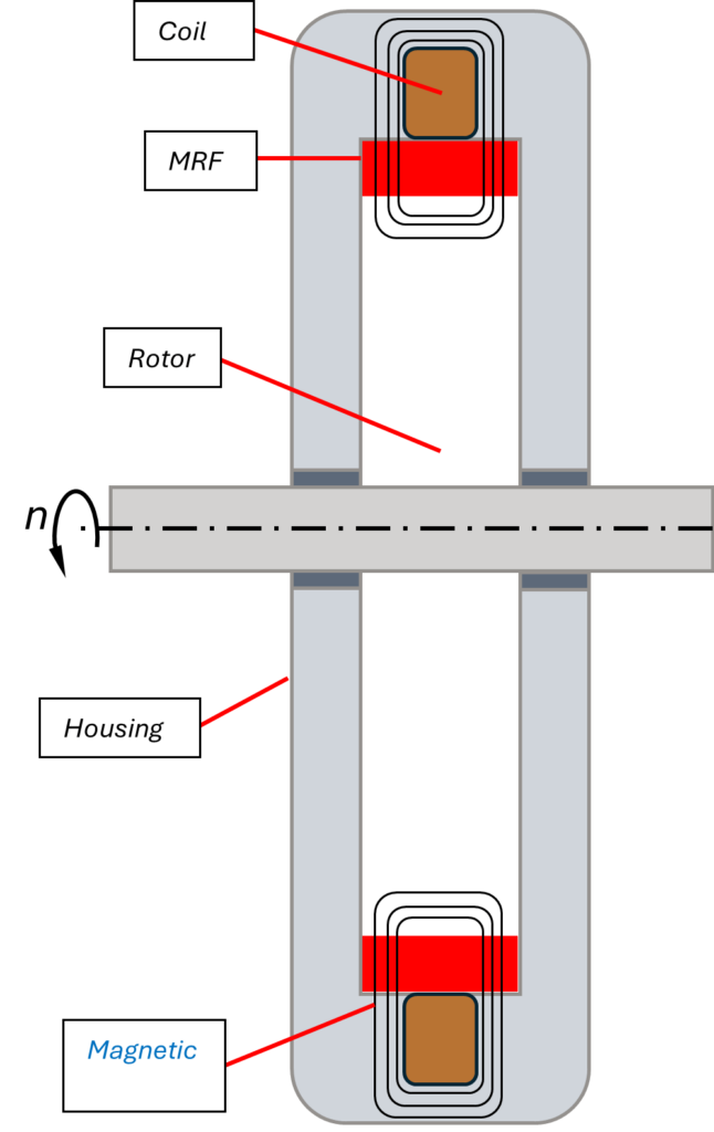
The illustration shows the second possibility of the technical design of a shear damper with the various main components, in which a rotor is rotatably mounted in a stationary housing in which the coil is integrated. 

The magnetic field closes all the way around the coil housed in the housing through the MRF via the rotor, similar to variant 1 in Fig. 5.

Cross-sectional view of an MRX shear damper, showing labeled components such as coil, MRF, rotor, magnet, and housing.
Figure 20: MRX shear damper in section (rotor turns in the housing)


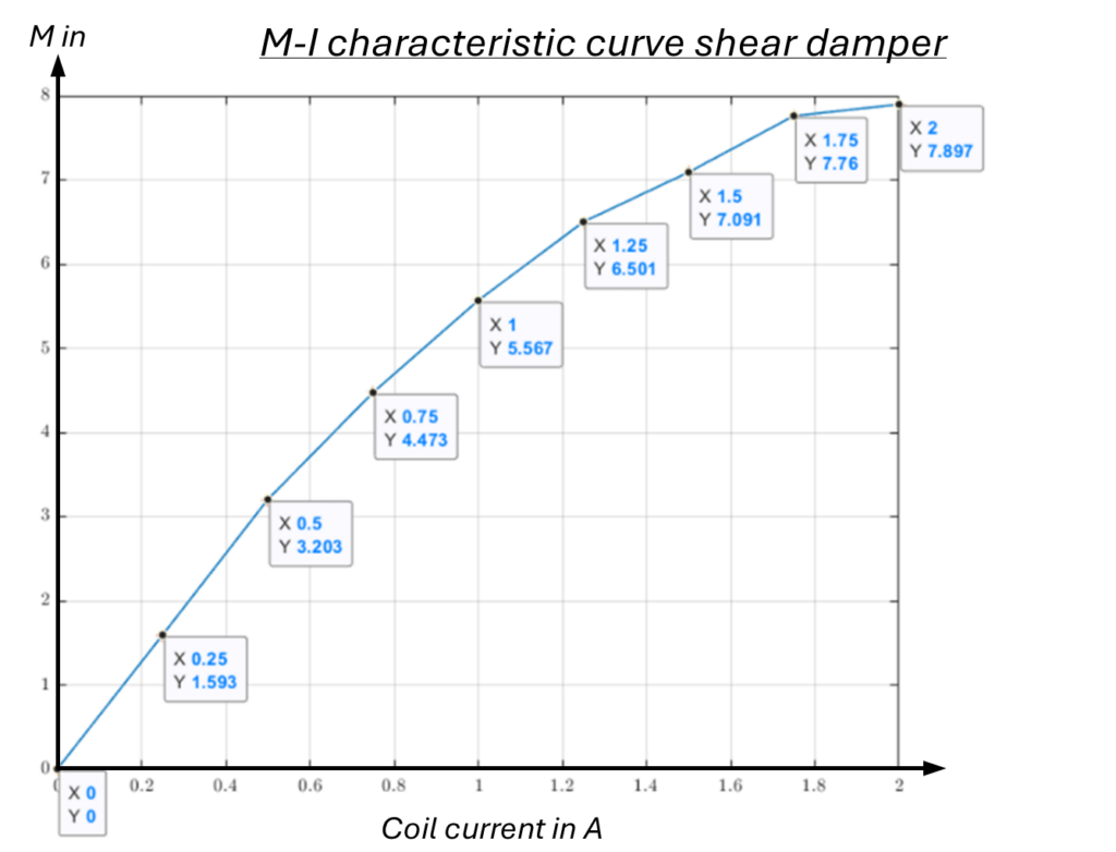
The M-I diagram with its degressive curve shows how the braking torque can be controlled via the current almost independently of the speed.

M-I characteristic curve of a shear damper, showing torque as a function of coil current with highlighted data points.
Figure 21: M-I characteristics curve of a shear damper

Here is an example of a successfully implemented products that use exactly this technology.

Steer by Wire

Inventus steer-by-wire system featuring ergonomic controls and advanced functionality.

Rotary Encoders

Inventus-in-touch-d60-01-web

Shear Mode - Star Contour

This section is password protected!

To get access to it, please contact Inventus-Development!

MRX-Shear Damper with Star-Contour:

In order to combine the two advantages of shear dampers and wedge bearings, we developed a modified shear damper and the result was the MRX shear damper with star contour.

Magnetic flux through the working gap of an MR shear damper with star contour, schematic representation of the area between the housing and the coil core.
Figure 25: Magnetic flux through the effective gap of an MR shear attenuator with star contour: area between housing and coil core

Here, a geometry introduced into the rotor or stator is used to align the MRX chains in a wedge shape similar to the wedge effect and increase the torque accordingly. With this concept, the magnetic field is also concentrated via the geometry in accordance with the available passage area. This technical design is predestined for haptic applications due to its very pronounced „definition“ (clean release or constant friction conditions around the circumference).

Wedge effect in an MRX shear damper with star contour, close-up of material deformation under torque M and direction n.
Figure 26: Wedge effect with MRX shear damper with star contour

A even more interesting detail:

A very interesting application of the MRX shear damper with star contour is currently the topic of stere-by-wire, where electromechanical actuators simulate a separate steering column.

The illustration below shows how a steering wheel flange-mounted to an MRX shear damper with a star contour can be used to haptically reproduce certain torque profiles when energized. The very fast response behavior during a simulated steering input, in which the steering wheel is first turned, then turned for a short time and finally released, is clearly visible. Also clearly visible is the small influence of the speed during the turn, where a very constant approx. 7 Nm is present, the subsequent over-turning (breaking of the wedge in the same direction) amounts to approx. ¼ of the locking torque (worst case – release in the same direction).

MRX shear dampers with a star contour can meet the very highest requirements for haptics in terms of very critical „stick-slip“ requirements, where other mechanical systems have long since reached their limits, and are also economical and energy-efficient!

Diagram of the simulation of a steering lock with a steer-by-wire system, showing torque (M) and current (I) as functions of time.
Figure 27: Recording test profile - stereo-by-wire

Wedge Mode / Wedge Bearing

The wedge mode is a further development of the shear mode; here, too, a magnetic field is applied to an annular gap filled with MR fluid, but in this version small cylinders are arranged in the relatively wide annular gap in the ring, similar to the planets of a planetary gearbox, with the difference that they can move freely.

Close-up of an MRF wedge bearing, showing the surface texture and radial patterns of the component.
Figure 22: MRF wedge bearing

These cylindrical intermediate elements cause the MRF particles to align themselves like wedges in the annular gap with their chain formation (see adjacent figure); these aligned elements spread the annular gap apart with their normal force components, so to speak, and thus generate considerably more friction in the system, while at the same time there is also a more concentrated magnetic field due to the partial passage surfaces. By utilizing these two effects (wedge and magnetic field concentration), significantly more locking torque can be generated.

Illustration of the wedge effect, showing force distribution and rotational motion in a mechanical system
Figure 23: Wedge effect

In the ¾ section shown, it is easy to see how the magnetic field is closed via the L-shaped bar over the rollers through the housing in a circle around the coil. 

3D cross-sectional view of an MRF wedge bearing, showing labeled components such as coil, housing, cylinder, rotor, and non-magnetic covers.
Figure 24: 3D view of MRF wedge bearing in section

Very high torques can be generated with the MRF wedge bearing, but it should be noted that the mechanical release torque also increases with increasing locking torque.

INQUIRY

Inquiry for: