
Holds at 0 W. Reacts in under 1 ms. Yields instead of breaking.
No motor, gearbox or spring-applied brake can do all three. The INVENTUS MR brake does – in one component, at a fifth of the installation volume.
Developed and patented by INVENTUS – a capability no one else offers.
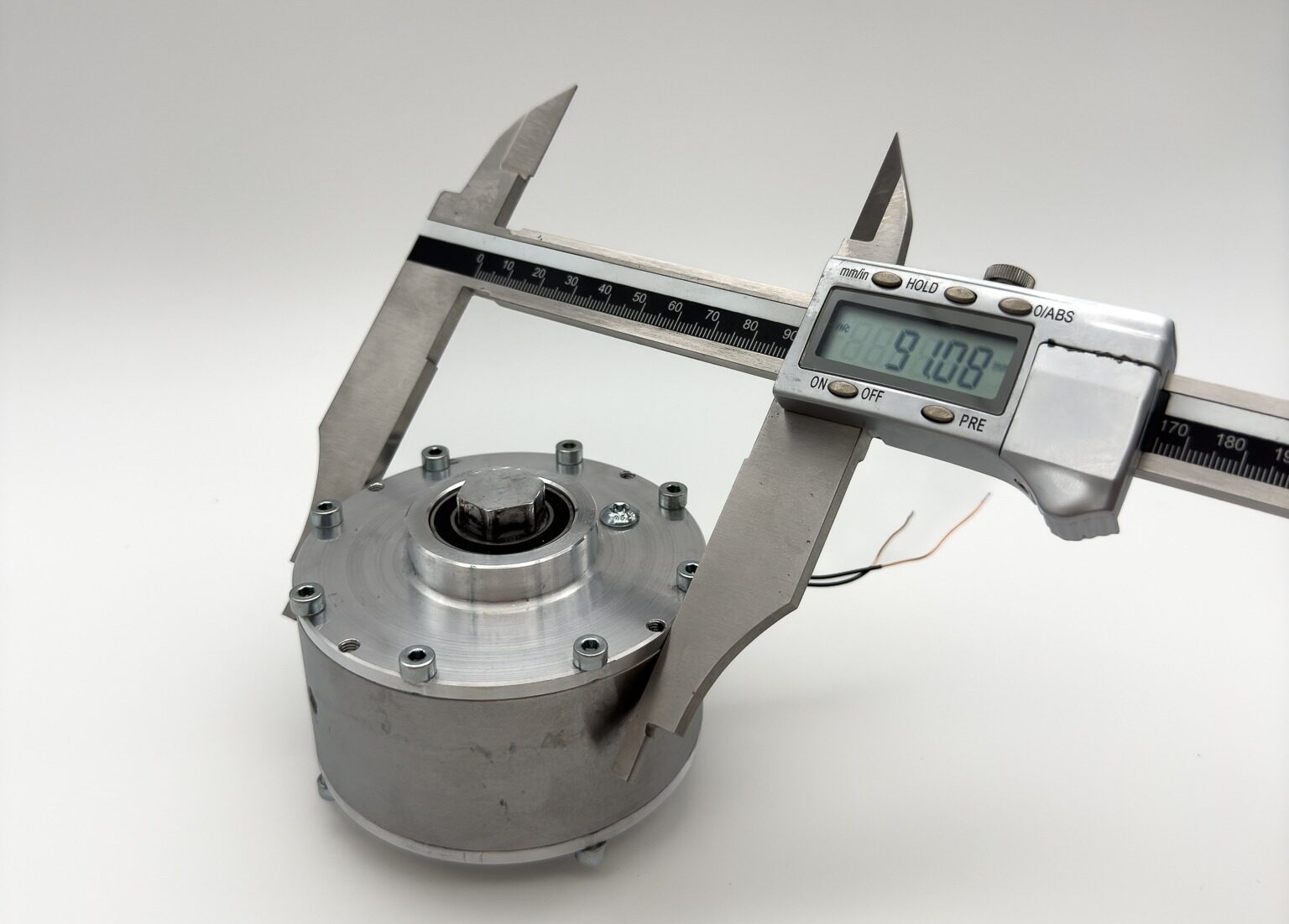 Real hardware
Measured, not simulatedEvery WP value on this page comes from a built and tested brakeDimensions, mass, basic friction, torque at 0.5–3 A, dynamic stops and the pulse test – documented with photos and videos on our test page.Open the test page
Humanoid robots spend much of their working time holding: carrying boxes, positioning parts, keeping a pose. For the electric motor, holding is the worst operating point – it draws current continuously, does no mechanical work and turns all the electrical power into heat. INVENTUS MR brakes take over exactly this job: they hold loads at 0 W, dose torque steplessly and protect gearbox and sensors against overload.
Challenge: holding heats the joint
Mechanical power is torque times angular speed. When a robot holds a box, the speed is zero – so is the useful power. The motor still needs current to produce torque, and current in the winding becomes heat: P = I² · R. Twice the holding torque means four times the heat.
Peak torque is the sprint, holding is the shift: the datasheet peak is available for seconds. After about 30 seconds the winding heats up and the firmware derates; for minutes, roughly half – often less – can be held. The honest question for a humanoid is not how much it can lift, but how long it can hold it.

80–100 °C
Typical winding temperature at which firmware reduces torque and payload or pauses the robot.
≈ 80 °C
Standard neodymium magnets in the motor can start to lose strength permanently – far below the Curie point.
3 kg → 2 kg
Payload per arm in simulation vs. real hardware before the wrist motors overheated (FALCON study).
Worked example: holding a 23 kg box
11.5 kg per arm, held 0.34 m in front of shoulder and elbow → about 38 Nm per joint (11.5 kg × 9.81 m/s² × 0.34 m). The motor's holding power depends mainly on the gear ratio:
| Gear ratio | Motor torque | Per joint | Four arm joints |
|---|---|---|---|
| 20 : 1 | 1.9 Nm | ≈ 160 W | ≈ 640 W |
| 30 : 1 | 1.3 Nm | ≈ 70 W | ≈ 285 W |
| 50 : 1 | 0.8 Nm | ≈ 26 W | ≈ 100 W |
| 100 : 1 | 0.4 Nm | ≈ 6 W | ≈ 26 W |
Holding power ≈ (joint torque ÷ (ratio × km))², km = 0.15 Nm/√W (typical inrunner, 70–85 mm); friction and electronics losses neglected. High ratios reduce holding power but cost efficiency, back-drivability and robustness against impacts. Sources: industry article "Thermal Management" (LinkedIn, 09/2026); Zhang et al., FALCON, arXiv:2505.06776.
State of the art: cooling, gearing – or an on/off brake
| Today's workaround | Its price |
|---|---|
| Heat into the structure | Hot surface, more mass |
| Phase-change material | Mass, needs time to recover |
| Liquid cooling | Pumps, leaks, maintenance, cost |
| Thermal software | Throttles performance |
| Very high gear ratio | Friction, poor back-drivability |
| MR brake while holding | No current – no heat |
Spring-applied holding brakes also hold at 0 W – but only on/off. They are designed for standstill and emergency stop, engage with a jolt and need current to stay open while the arm moves.
Solution: a second torque path in the joint
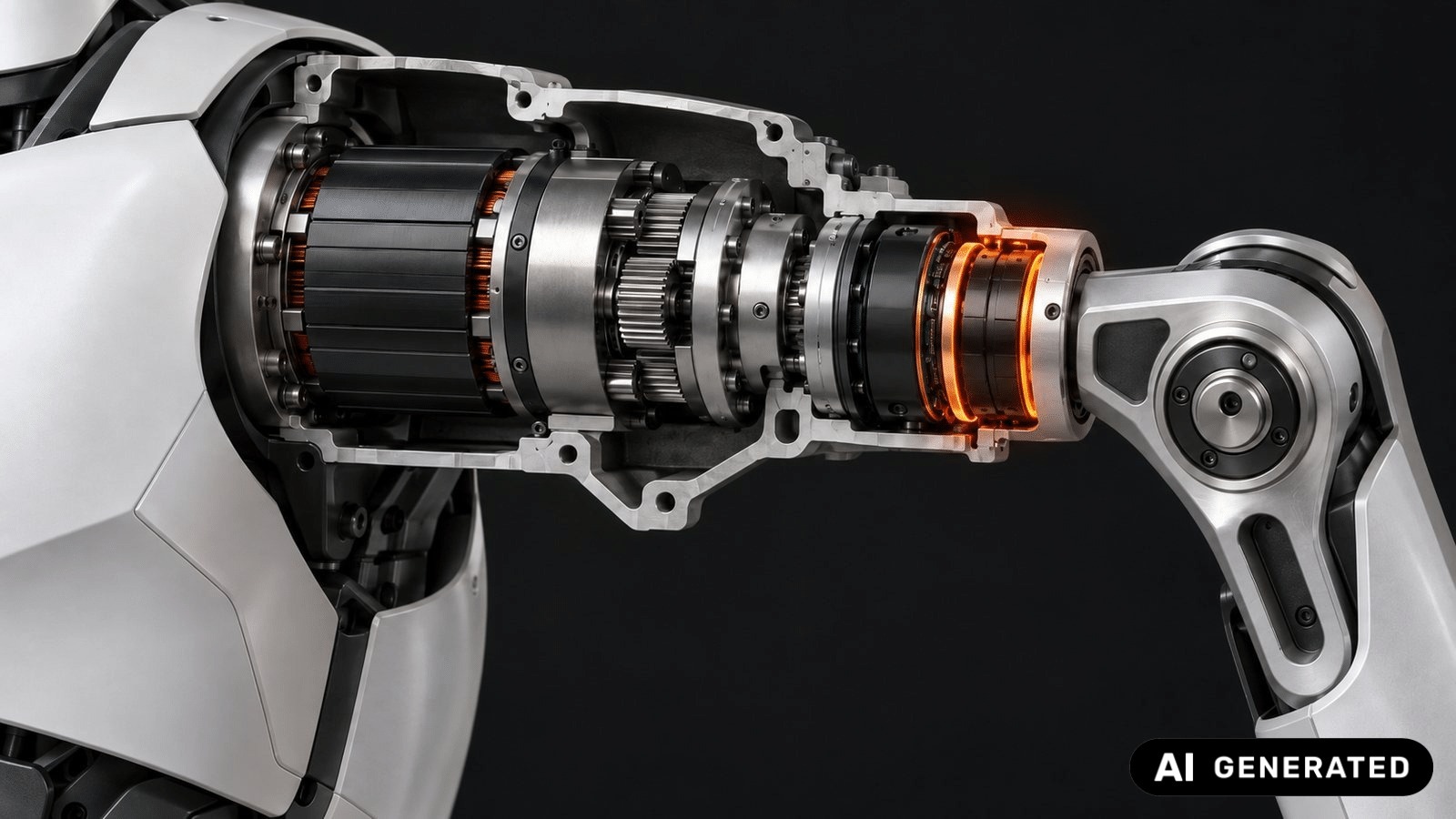
The INVENTUS MR brake sits as a parallel path between joint output and housing. It replaces neither motor nor gearbox – it takes over exactly what the electric motor is physically bad at.
Move – motor and gearbox
Accelerate, position, do mechanical work.
Hold – MR brake
Hold the load without motor current – 0 W with permanent magnet.
Yield – MR brake
Slip in a controlled way under overload instead of blocking – nothing breaks.
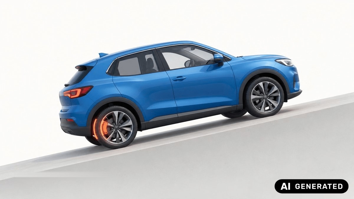
With the MR brake engaged
The MR brake carries the load mechanically – like the handbrake of a vehicle. The motor controller ramps the current to zero: no holding power, no heat, no thermal derating. (Example: four arm joints, gear ratio 30 : 1.)
One carrying cycle
1 · Handover: the brake closes, then the motor current ramps to zero – the load hangs on the brake.
2 · Placing: the brake opens smoothly and without a jolt. If placing is gravity-driven – i.e. braking – the MR brake does it itself, with very little current and with fine haptic control.
The longer the hold, the larger the saving. While moving, the brake needs 0 W (switchable magnet) or a few watts (permanent magnet + coil).
How the INVENTUS MR brake works
Move the slider – switch the field on
Schematic view of the active gap. The coil drives a magnetic field through housing, gap and rotor – the field lines (arrows) cross the whole gap. The carbonyl iron particles magnetise and line up head-to-tail along the flux: the particles attach to the poles first and the chains grow from N and S towards the middle of the gap until they bridge it; with more field, more and thicker columns – within < 1 ms. The columns transmit shear stress and brake the rotor steplessly; torque rises with the flux up to magnetic saturation. One short pulse re-magnetises a switchable magnet: the brake then holds without any current.
A rotor and a housing are separated by an active gap of less than 1 mm, filled with dry carbonyl iron powder. Without a magnetic field the powder is loose. With a field, the particles form chains that transmit shear stress: braking torque = shear stress × active area × radius. More field means more torque – steplessly, not just on/off.
Everyday analogy: vacuum-packed coffee – loose powder, yet hard as a brick once the air is out. In the MR brake, the magnetic field is the vacuum.
Temperature independent
Powder only, no carrier fluid: no temperature-related change of torque caused by the medium. Usable up to approx. 300 °C.
Pressureless and sealed
Nothing settles, nothing leaks – and no abrasion dust as with friction brakes.
Minimal base torque
< 0.3 Nm for the larger WP brakes, < 0.1 Nm for smaller MR brakes – below 1 % of the holding torque. High efficiency, easily back-drivable, no disturbance of joint torque measurement.
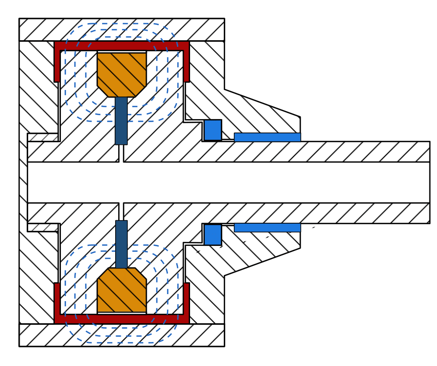
- Housing (stator) and rotor – hatched; the rotor turns with the joint
- Coil – low voltage, a few amps, PWM-controlled
- Active gap < 1 mm – filled with carbonyl iron powder
- Magnetic circuit – closes from rotor across the gap to the stator
- Bearings and seals – the shaft can be hollow for cables
- Permanent magnet (option) – holds at 0 W
Four ways to create the field
| Variant | A · Coil only | B · Permanent magnet + coil | C · Switchable magnet | D · Switchable magnet + coil |
|---|---|---|---|---|
| Principle | Current sets the torque (0–6 A, PWM) | Magnet holds; reverse current cancels the field steplessly | Short pulse (< 1 s) re-magnetises permanently | Pulse-generated field, strengthened or weakened by the coil |
| Holding | Current needed (≈ 30 W at 38 Nm, WP D80) | 0 W | 0 W | 0 W |
| Braked motion | Stepless in real time by varying the current | Stepless in real time by varying the current | Stepless in real time by varying the current | Stepless in real time by varying the current |
| Free motion | 0 W | Coil current to open | 0 W | 0 W |
| Power failure | Opens | Closes – like a parking brake | Keeps last state | Keeps last state |
With B to D, the coil additionally strengthens or weakens the magnetic field – for fine and smooth motion and braking.
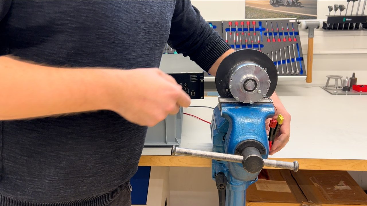 Lab video · 1:14
Variant C in the labPulse test: one 200 ms pulse, 140 Nm – held without any energy supplyA switchable permanent-magnet element is re-magnetised by a single pulse (≈ 160 W for ≈ 200 ms) and holds ≈ 140 Nm afterwards at 0 W – measured on the WP brake.Watch the pulse test
Comparison with the state of the art
Same robot, same box – with and without MR brake
All figures refer exclusively to the shoulder and arm joints shown – the leg joints used for walking are not included. Joint temperature and battery level are shown schematically.
Both robots run in sync. Picking up and placing cost the same – the motor does the lifting. While carrying, the four motor-only arm joints keep drawing ≈ 285 W in total (gear ratio 30 : 1) and turn all of it into heat – and the hotter the windings get, the more power they need for the same torque (copper resistance rises ≈ 0.4 % per kelvin). The MR brakes hold the load at 0 W and the joints cool down.
Versus the spring-applied holding brake
Robot and gearbox manufacturers use spring-applied holding brakes for power-off holding today. Comparison in the 38 Nm class:
| Parameter | Spring-applied holding brake | INVENTUS WP D64 |
|---|---|---|
| Holding torque | 38 Nm | 35.9 Nm |
| Outer dimensions | Ø167.5 × 25 mm | Ø64 × 35 mm |
| Envelope volume | 0.55 L | 0.11 L |
| Mass | 3.1 kg | 0.70 kg |
| Torque / volume | 69 Nm/L | 319 Nm/L |
| Torque / mass | 12.3 Nm/kg | 51.3 Nm/kg |
| Torque | On / off | Stepless |
Spring-applied brake: manufacturer datasheet. WP D64: measured braking torque. Volume: envelope cylinder from outer dimensions. 0 W holding: permanent-magnet version.
More than holding: hold, dose, release, protect
| Property | Spring-applied holding brake | INVENTUS MR brake |
|---|---|---|
| Holds without power | Yes | Yes (permanent magnet) |
| Power while the arm moves | Current needed to stay open | 0 W with switchable magnet |
| Torque | On / off only, with a jolt | Stepless 0–100 % |
| Engaging during motion | Emergency stop only | Normal operation |
| Load handover to the motor | Abrupt | Smooth and controlled |
| Overload (fall, collision) | Blocks or slips undefined | Slips at the set limit torque – without damage |
| Haptics and sensitivity | None | Fine, stepless dosing |
Torque per volume
WP series: measured braking/holding torque · robot actuators: peak values according to manufacturers · volume from published outer dimensions
The advantage lies in installation volume and in permanent holding without power. In terms of weight (44–63 Nm/kg), WP without gearbox reaches the level of good robot actuators with gearbox.
Little material – low cost and energy: high torque density needs little iron, copper and powder. This reduces weight and material cost by factors – the more efficiently the material is used, the more economical the component. And the lighter the component, the less mass the robot has to lift and accelerate: it becomes more energy-efficient.
Built and tested – and freely scalable
| Size | Torque | Dimensions | Mass | Nm/L | Nm/kg |
|---|---|---|---|---|---|
| WP D64 | 35.9 Nm | Ø64 × 35 mm | 0.70 kg | 319 | 51.3 |
| WP D80 | 60 Nm | Ø80 × 40 mm | 1.35 kg | 298 | 44.4 |
| WP D91 | 125 Nm | Ø91 × 70 mm | 2.0 kg | 275 | 62.5 |
Built and tested INVENTUS MR-WP actuators – values measured. MR actuators are freely scalable: diameter, width and torque are adapted to each joint, as torque grows with active area and radius. Slim MR actuators with approx. 20 mm diameter for hand and finger joints are in development.
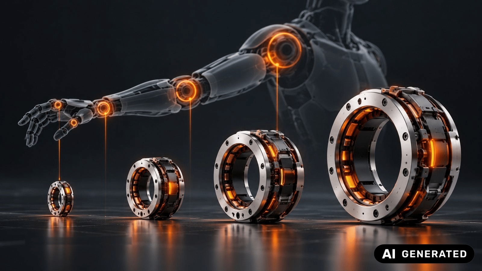
Integration, overload protection and fail-safe
A · Output side
Braking torque = joint torque (≈ 38 Nm → WP D80).
+ Bypasses the gearbox: protects gearbox and torque sensor against falls and impacts.
− Larger, heavier unit in the arm.
B · Motor side
Braking torque = joint torque ÷ ratio (38 ÷ 30 ≈ 1.3 Nm).
+ Small and light (only ≈ 1.3 Nm) – the lean energy-saving solution.
− The gearbox carries the load; no impact protection.
Integrated overload protection
Above the limit torque, the MR medium slips through without damage – the impulse goes directly into the housing, bypassing torque sensor and gearbox. The limit torque can be set by software; no reset is needed afterwards.
Torque sensor
Problem: strain-gauge sensors break under overload.
MR solution: the brake limits the torque – the sensor stays within its measuring range.
Strain-wave gear
Problem: reflected inertia grows with i² – an impact or fall can destroy the gear.
MR solution: decoupling plus controlled damping; the energy goes into the housing – also during falls and power failure.
Human contact: inertia
Problem: even with the motor switched off, high system inertia can hit a person in a fault.
MR solution: fast, stepless decoupling and defined braking – immediately ready again.
Human contact: malfunction
Problem: with a fully energised motor due to a malfunction, an arm has the striking force of a horse's hoof.
MR solution: the MR brake is always designed stronger than motor plus gearbox and brakes this "lash-out" to zero.
Fail-safe by design: the safe torque is built into the hardware
Motor, MR brake and control active
Power, control unit or sensor fails
Buffer battery, permanent or switchable magnet
Hold, damp, lock – or release in a controlled way
1 · Buffer battery
Keeps active control for a defined time – e.g. to set the load down in a controlled way.
2 · Permanent magnet
Passive base torque without power, software or communication – instantly available.
3 · Switchable magnet
Bistable: switched by a short pulse, then stable without energy. Already tested: one 200 ms pulse, 140 Nm – held without any energy supply.
Lab videoWatch the pulse test140 Nm from one pulse – video from our lab"Power-off" is not automatically "safe": the safe state is defined per joint, designed for the worst case and validated. Redundant sensors, coils or electronics add further fault tolerance.
The robot hand: many small joints – each must hold
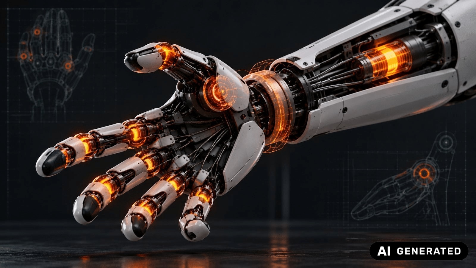
A humanoid hand needs 5–10 independently holding actuators – highly dexterous hands up to 25. Per robot that means 10–20 brakes, in extreme cases up to 50. In hand and forearm, space and mass are extremely limited – this is where direct torque density without gearbox counts most.
Move
The motor moves finger and tendon – efficiently, as it is built to.
Hold
Grasped objects are held without continuous current – even during a power failure the hand does not let go.
Yield
Yields in a controlled way under overload – protects motor, gear, tendon and object.
In a tendon-driven hand, the MR element sits in the forearm on the cable axis, where space is available: motor → pulley/gear → MR holding element → tendon → finger. For wrist, thumb base and larger finger axes, a small ring-shaped MR brake directly around the joint axis is also conceivable.
| Challenge | Contribution of INVENTUS MR | System benefit |
|---|---|---|
| Long gripping and holding | Holding without continuous current | Lower battery consumption |
| Motor heating at standstill | MR takes over the static torque | Less heat, less derating, smaller motors |
| Power failure | Passive holding torque | Object is not dropped |
| Different objects | Steplessly adjustable torque | Adaptive grip force and haptics |
| Collision and overload | Controlled slip | Protects tendon, motor, object and people |
| Extremely limited space | High direct torque density | Compact integration in hand and forearm |
| Dynamic interaction | MR effect < 0.8 ms | Fast changes of haptics and impedance |
Transferring the torque density to very small finger actuators is being demonstrated in design and test. System response time also depends on coil, electronics and control.
Proven in series – protected worldwide
Steer-by-wire and the robot joint share the same task: holding high torques without power and dosing them finely. INVENTUS MR technologies are protected by granted patents worldwide – a head start for market entry and a strong argument in a market that will be fiercely contested.
Prospect
Power-off, energy-efficient holding is a must for humanoid robots. The brakes needed for it must be combined with motor and gearbox into one fully integrated, compact and light component – which is only possible with brakes of high torque density and efficiency. In the hand, with even less space and weight, this matters even more.
INVENTUS will be happy to work with you to develop the ideal MR brake for your robot joints – from finger to hip.
Contact us – office@inventus.at